Kodak Carousel Remote
My partner had an exhibition recently in Berlin, and the work she wanted to show was a series of pencil drawings, captured on 35mm film and projected using an old slide projector. She has a 35mm film camera and a projector, but the problem was that she had no way to control the movement from one slide to the next.
The projector had a (wired) remote with buttons for forward and back, but it has no way to set a timer. This exhibition would run for weeks, and it wouldn’t exactly be practical to have someone stand around pressing the ‘forward’ button every 30 seconds. Thanks to my newly found courage when it comes to hardware tinkering, and the support network of the folks at the Pixelbar, I said I’d take care of it.
Initial thoughts
I knew that I wanted to be able to:
- Advance from one slide to the next
- Reverse through the carousel, back to the beginning
- Adjust the time in between slides
I also knew that because the remote was wired, it must work by just closing loops on different circuits with each press of the different buttons. Thankfully, Kodak published the circuit diagrams for their products back in the day, and I was able to confirm this by taking apart our particular remote.
I knew that the remote connected to the projector using an 8 pin connector of some variety.
The Plan
The plan was to create a device that would mimic the wired remote control, would be programmable, and would advance the slides at a set interval. This device would connect to the same port as the existing remote control (by splicing the remote control cable if necessary).
The heart of the device would be an Arduino. Its a low power, low cost device, has plenty of pins to connect things to, and there’s a plethora of knowledge available online.
I would need some way of triggering the ‘buttons’, i.e closing the circuits for the different functions (in retrospect I know this is very basic stuff, but I’m new to this hardware world), and the whole thing would need to be packaged up in a way that would be relatively discreet.
The Build
Turns out that the 8 Pin connector that the wired remote used is a pretty standard DIN connector, the same connector used by MIDI cables, so I ordered a cheap MIDI cable that I could cut in half, using the exposed wires on one to interact with whatever device I would make. This also had the benefit of leaving the original remote intact and unadulterated by this whole process.
At this point I had the interface with the projector sorted, next we needed to focus on the actual device itself.
Of the 8 pins on the remote cable, one is used to provide a common voltage shared across all the functions, one controls the ‘forward’ action, one controls the ‘back’ action, there are two dedicated to focussing the lens (which is something I figured could be done by hand on the projector itself and was outside the scope of this project), one pin is for ground and the remaining two are not used for anything.
I would need to connect the common wire and the wire of whichever action I wanted in order to make the projector do what I needed. The name for this component is a relay, and you can think about it just like a switch.
You can think about a relay as being split into two parts, the bit that takes instructions (in my case this would be connected to the Arduino) and the bit that distributes power (this will be connected to the projector). The instruction side of the relay has an input for power, an input that tells it what to do (control voltage), and an output to ground. The distribution side of the relay has three connections, one for the incoming voltage, and two outputs that the switch will swap between.
In my scenario the incoming voltage would be coming from the projector via the common wire, the control voltage would come from the Arduino, and the two different outputs would return to the projector via either the ground (do nothing) circuit, or the ‘advance’ circuit (advance the slides). Repeat the process for the ‘reverse’ action and we have the basis of a feasible solution.
The first problem was that I only had one common wire, and I needed two switches. I didn’t know enough about electricity and wiring to know if I could split the common wire and use this split wire as input into both relays, so I decided against that. What I settled on was, I think, a more elegant solution.
- The common voltage from the projector (Yellow wire) enters Relay A’s input.
- Relay A’s default position is ‘off’, i.e do nothing, which pushes the current through it’s output 1.
- Output 1 of Relay A is connected to the input of Relay B.
- Relay B’s default position is also ‘off’, which pushes the current through it’s output 1.
- Output 1 of Relay B is connected to the ground (black wire) running back to the projector
The relay is controlled by passing a voltage to it’s control input. When you send a voltage (in the case of the relays I used, 5V) over a wire connected to this input, the relay switches from passing current through output 1, to passing it through output 2 instead. When you remove the voltage from the control input, the switch closes and current passes through output 1 again.
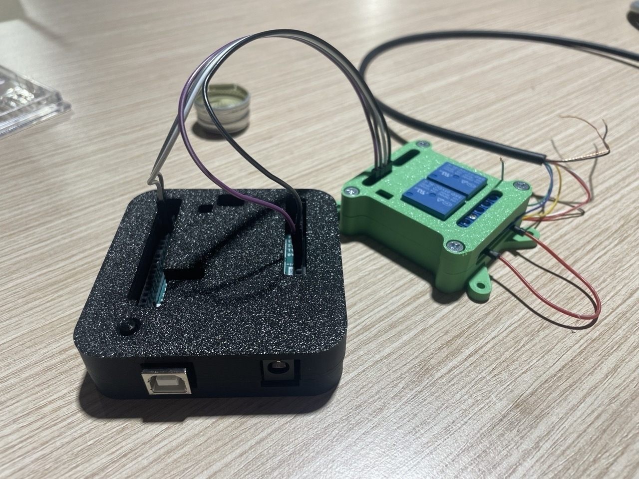
The relay I used was a 2-channel relay that I got from Kiwi Electronics. By having essentially 2 relays on one board, I only had to worry about one “instruction side”, which would receive power from the Arduino, and would accept two control voltages, one responsible for each relay on the board.
Once all this was wired up and connected to the Arduino, I needed to write a simple program that would toggle the relays on/off at the desired interval. The project contained around 30 slides, and the carousel has room for 80, so I needed to quickly reverse back to the start once we reached the end (rather than moving forward and cycling through 50 blank slides).
The following is the finished program, it’s pretty basic and could probably be tidied up a lot, but it works!
// start by initializing the pins that will control the relays, and some variable that lets the program know if this is the first run - or subsequent runs. The reason being that for the first run we want a delay before starting everything, every subsequent run there should be no delay. There's also a variable to keep track of which slide we're on.

int ch1Pin = 2;
int ch2Pin = 3;
int ssrON, ssrOFF;
int firstTimeRun = 1;
int current_slide = 0;


// This is where we configure the length of the delays between slides, expressed in milliseconds
int text_delay = 18000;
int img_delay = 2000;
int rev_delay = 2000;


//Here we set the mode for the pins, in this case want to use them as outputs, and set them both to OFF for the time being
void setup() {
  Serial.begin(9600);
    pinMode(ch1Pin, OUTPUT);
    pinMode(ch2Pin, OUTPUT);
    ssrON = LOW;
    ssrOFF = HIGH;
    digitalWrite(ch1Pin,ssrOFF);
    digitalWrite(ch2Pin,ssrOFF);
}


// This is core of the program, with a run plan with specific timings and a few debug messages coming over Serial.print() so that I could keep track when figuring out timings. It took a little time to figure this out, as too short a delay between instructions will be misinterpreted as single action, rather than two.
void loop() {

        Serial.print("Projecting Slide: ");
        Serial.print(current_slide);
        Serial.println();

    if(firstTimeRun == 1){
      delay(5000);
      firstTimeRun = firstTimeRun + 1;
        for(int i=0;i<13;i++){
        forward();
        Serial.print("Projecting Slide: ");
        Serial.print(current_slide);
        Serial.println();
        delay(text_delay);
      }
    }
    else{
        for(int i=0;i<12;i++){
        forward();
        Serial.print("Projecting Slide: ");
        Serial.print(current_slide);
        Serial.println();
        delay(text_delay);
      }
    }


    for(int i=0; i<8;i++){
      forward();
      Serial.print("Projecting Slide: ");
      Serial.print(current_slide);
      Serial.println();
      delay(img_delay);
    }

    for(int i=0; i<7;i++){
      backwards();
      Serial.print("Projecting Slide: ");
      Serial.print(current_slide);
      Serial.println();
      delay(rev_delay);
    }

    for(int i=0; i<7;i++){
      forward();
      Serial.print("Projecting Slide: ");
      Serial.print(current_slide);
      Serial.println();
      delay(img_delay);
    }

    for(int i=0;i<13;i++){
      forward();
      Serial.print("Projecting Slide: ");
      Serial.print(current_slide);
      Serial.println();
      delay(text_delay);
    }

    for(int i=0; i<33;i++){
      backwards();
      Serial.print("Projecting Slide: ");
      Serial.print(current_slide);
      Serial.println();
      delay(rev_delay);
    }

}

//I separated the forward and back actions to their own separate functions, and call them from within the main function whenever I need them
void forward(){
      digitalWrite(ch2Pin,ssrON);// turn relay SSR2 ON
      delay(200);// wait for .2
      digitalWrite(ch2Pin,ssrOFF);// turn relay SSR2 OFF
      current_slide++;
}

void backwards(){
      digitalWrite(ch1Pin,ssrON);// turn relay SSR2 ON
      delay(200);// waite for .2
      digitalWrite(ch1Pin,ssrOFF);// turn relay SSR2 OFF
      current_slide--;
}
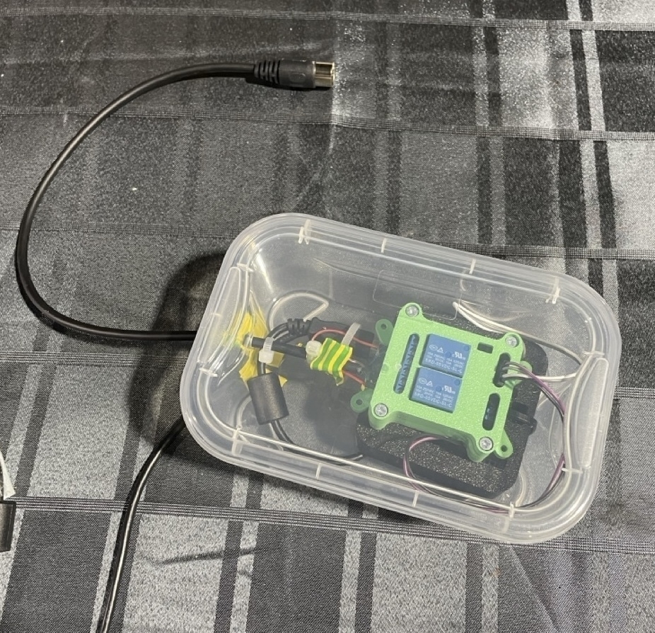
With the hardware built and the software working, the only thing left to do was create a rudimentary housing for everything. I 3D printed a case for the Arduino, and another for the relay unit and glued these two parts together. I then packaged the whole thing in a small, clear plastic lunchbox with a hole drilled through for the MIDI and power cables. A few cable ties and some hot glue ensured that nothing could move around or come loose during transit. It’s rough and ready, but it works and is secure!
The feedback from Elle has been really positive, the system worked perfectly at the show in Berlin (even if I forgot to pack a USB power adaptor and she had to run around the city trying to find one on her install day, my bad!), and it’s really made me a lot more confident taking on hardware projects in the future.